Replicating D-POINT
Published: 25 Nov 2023
Last week, Leo asked me if I would like to join the How to Make Machine Building week at CBA MIT. I considered splitting my optical tracking system from the CAMap project I did earlier this year. This alone deserves a blog post, but long story short, two people sent me a link to the D-POINT project on the same day and asked if this is something I am working towards, too.
As stated in the README on the project GitHub repository D-POINT is an open-source digital stylus that uses camera tracking and inertial measurements to achieve 6DoF (six degrees of freedom) inputs with low latency, pressure sensitivity, and sub-millimetre accuracy. The stylus can be used on any flat surface and with consumer-grade webcams. I decided to try replicating it, and this post documents the process.
I found out more about the project and its author. It appeared to be a thesis by a person whose GitHub handle is Jcparkyn, and it maps to James Parkyn in the real world. I found a way to send him a message and asked if it would be possible to read his thesis? A day later, I had the PDF version of it. “Six-Degrees-of-Freedom Digital Stylus with Visual-Inertial Tracking” – bachelor’s thesis by James Parkyn, published on October 2023, University of Tasmania, School of Engineering.
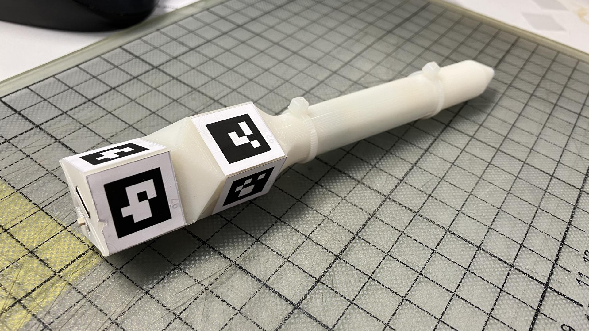
Meanwhile, I soaked up the information from the README. D-POINT uses 2x2 cm printed fiducial markers placed on the top end of a custom-made stylus pen. It also features a force sensor (Alps Alpine HSFPAR003A) that is read by the XIAO nRF52840 Sense and sent to a computer via Bluetooth connection. The XIAO nRF52840 boards are the perfect choice for Bluetooth connectivity. I tried pairing my phone with one of the boards earlier this year and was impressed by how easy it was.
I extracted some possible pros and cons of the system.
The Pros
- Uses off-the-shelve consumer-grade USB camera.
- Fiducial marker placement is less likely to obstruct the tracking camera as it is above one’s hand.
- Millimeter precision and pressure sensitivity with minimal hardware.
The Cons
- Complex calibration (fiducial placement on pen and camera calibration).
- Limited distance (fiducials are small, and the camera has to be close to see them).
- Lightning condition variability (needs fine-tuning as auto-adjustment is disabled).
Anyhow, the pros and cons above are hypothetical. How about I replicate the thing myself? The repository is made for that, and the only part I was missing was the force sensor. It is stated in the documentation that Alps Alpine HSFPAR003A or HSFPAR004A (preferred) should be used. I found HSFPAR003A on Mouser and ordered 10 of them for free shipping and “just in case”. While it arrives, I can focus on other parts, such as 3D printing and the PCB.
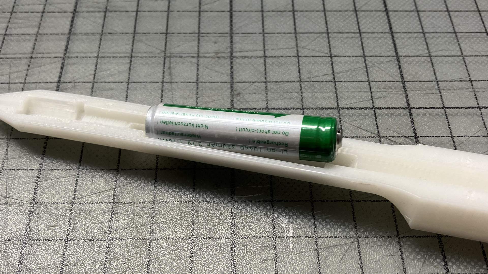
Another tricky piece of hardware is the battery. Li-ion batteries are popular, but the AAA or 10440 size with 3.7V voltage proved challenging. At the end of a long evening, I discovered suomenakut.fi. There is precisely one battery waiting for me in their Vantaa store, which is 50 minutes away by public transport from where I live.
Starting the Build with 3D Printing
3D printing should be easy. It took me roughly an hour to 3D print the top and bottom parts of the stylus with Prusa Mini+ printers at the Aalto Fablab. Still, I experienced some warping, so I will probably redo the printing with either a brim or one of our Formlabs printers and basic white resin. Maybe less infill and a brim will help. I will first try that and then move to the Formlabs printers.
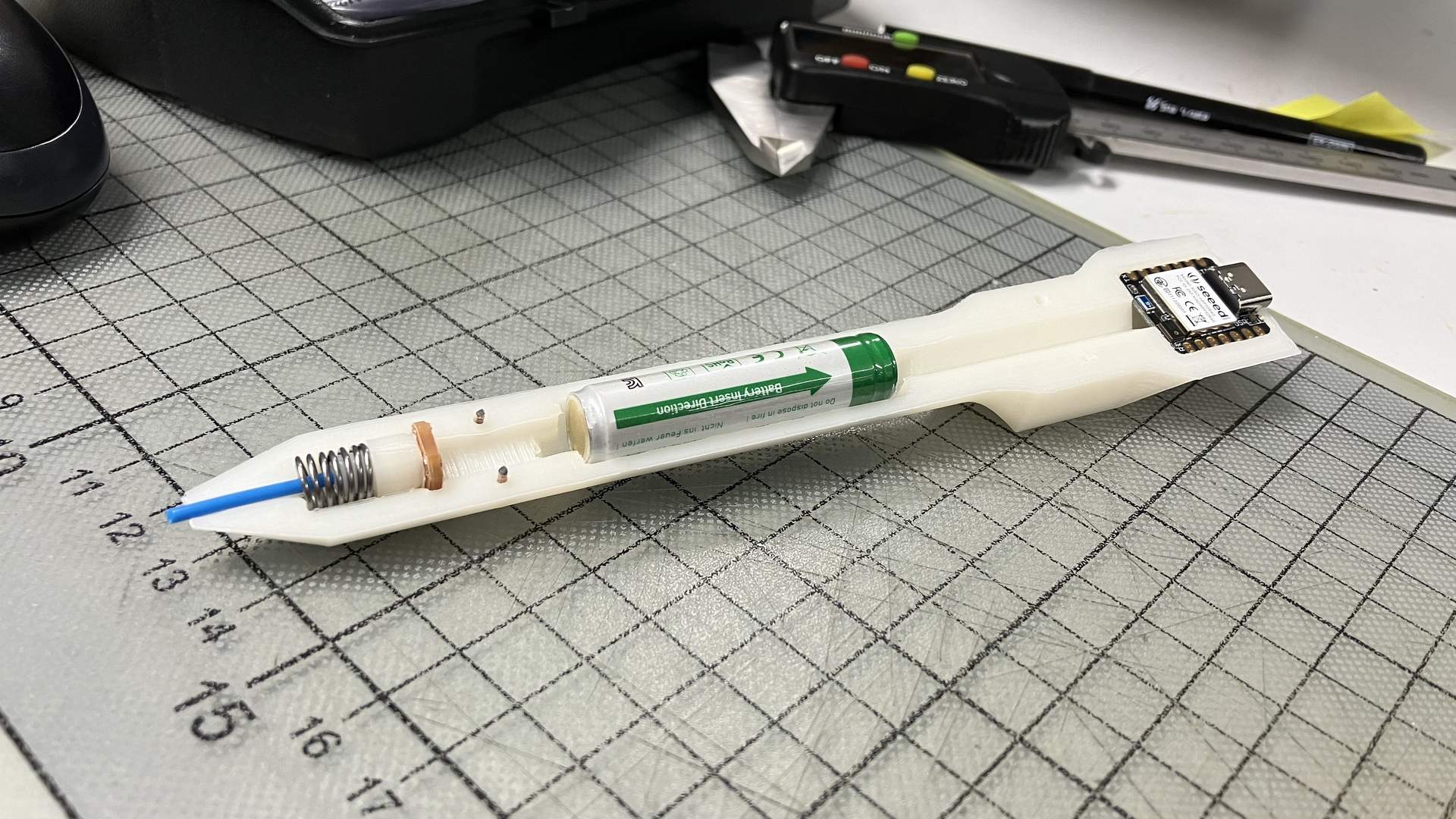
Another issue surfaced when I got the battery. Even though it is the same size as in the D-POINT docs (10440), it was a bit too long for the enclosure. The slot is 44.7mm long, but I got a 48.3mm battery. I would still leave some space for the springy metal terminal parts as I want to sell the battery directly to something other than wires. Thus, I would like to extend the length of the slot up to 50.0mm.
The solution for that is either adjusting the existing design of the stylus or making a new one. Several files with the .ipt extension can be found in the ‘print’ folder. ChatGPT told me it is the file format associated with Autodesk Inventor software. I do not use Autodesk Inventor for my CAD tasks, and I do not intend to start using it because of this project, but I also found a .step file that could be opened in software I use and modified a bit. While this is sufficient for replication purposes, what I ultimately wish is a more accessible design. I am considering a redesign of the stylus in OpenSCAD if my replication attempts are successful.
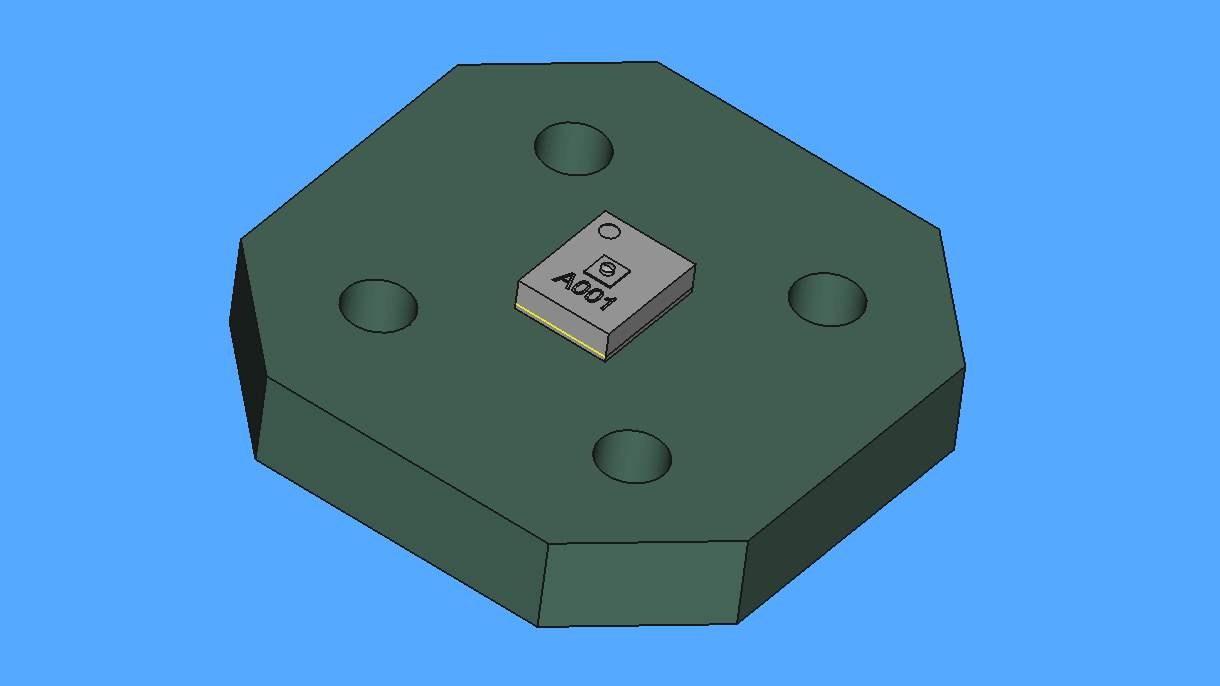
I fired up FreeCAD and loaded the dpoint.step file. It appears that it is just the circuit board with the sensor on it, probably exported from KiCad.
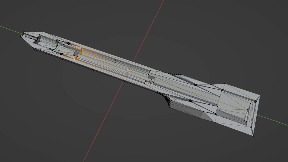
Still, there are the .stl files that can be loaded in a 3D mesh editing software and adjusted there. How about I use Blender to do the needed adjustments? I fired up Blender and imported one of the meshes. It appeared to be a very manageable mesh. Before proceeding with modifications, I made sure that the Unit System is set to Metric in scene properties, as well as length is measured in millimeters and that requires the Unit Scale to be set to 0.001. It should be possible to see the Length along Y axis of the stylus to be 165mm. It was a matter of entering the mesh editing mode and moving the endpoints of the battery slot 2.5mm backwards and 2.8mm forward.
I set the print up with brim this time to prevent the fold-up of the tip of the pen. I avoid using the brim whenever possible, but this time, it seems like I have to. I had to spend a bit extra time to remove the brim, but at least the result was not warped this time. The battery and all other parts fit well this time, and it is also possible to put the top and bottom parts together without having a gap between them.
One more issue remains. How to hold the two parts together? It seems that there are some pinholes, four on each of the stylus body sides, that are matching and probably are supposed to be used for fastening. I would prefer not to glue the two parts together, thus maybe another modification that would add screw holes is needed here. But again, just for the sake of moving forward faster, I will use the holes for alignment and add a pair of zip-ties to hold the enclosure together. 1.2mm diameter paper clips proved to be useful as alignment pins when cut.
Before looking for a 6.5x10.0mm spring, I managed to make one myself. When assembled together, the setup looks a bit different from the one in HSFPAR003A application note. In the case of the application note example, initial force is applied using a spring and pressure applied to the nib of the stylus reduces the force. On the contrary, in the D-POINT stylus, force is pre-applied using spring tension, and it increases as the user uses the stylus. I wonder if this is a potential design flaw and if it has been fixed and could it be that the final CAD files are not uploaded to the repository? I will find out, I guess.
I do not like the idea of soldering the power cables directly to the battery terminals. I set out to modify the design to add slots for battery terminals, which would be two bent slices of metal that would sit into dedicated slots on both sides of the battery. The folding of the metal plates would make the battery to snug-fit. First, I used Blender to add the needed modifications.
Then, I 3D printed the new enclosure. I cut some metal pieces and bent them in V profile so that the valley of the V would reach into the battery compartment and touch the battery terminals.
Electronics Integration
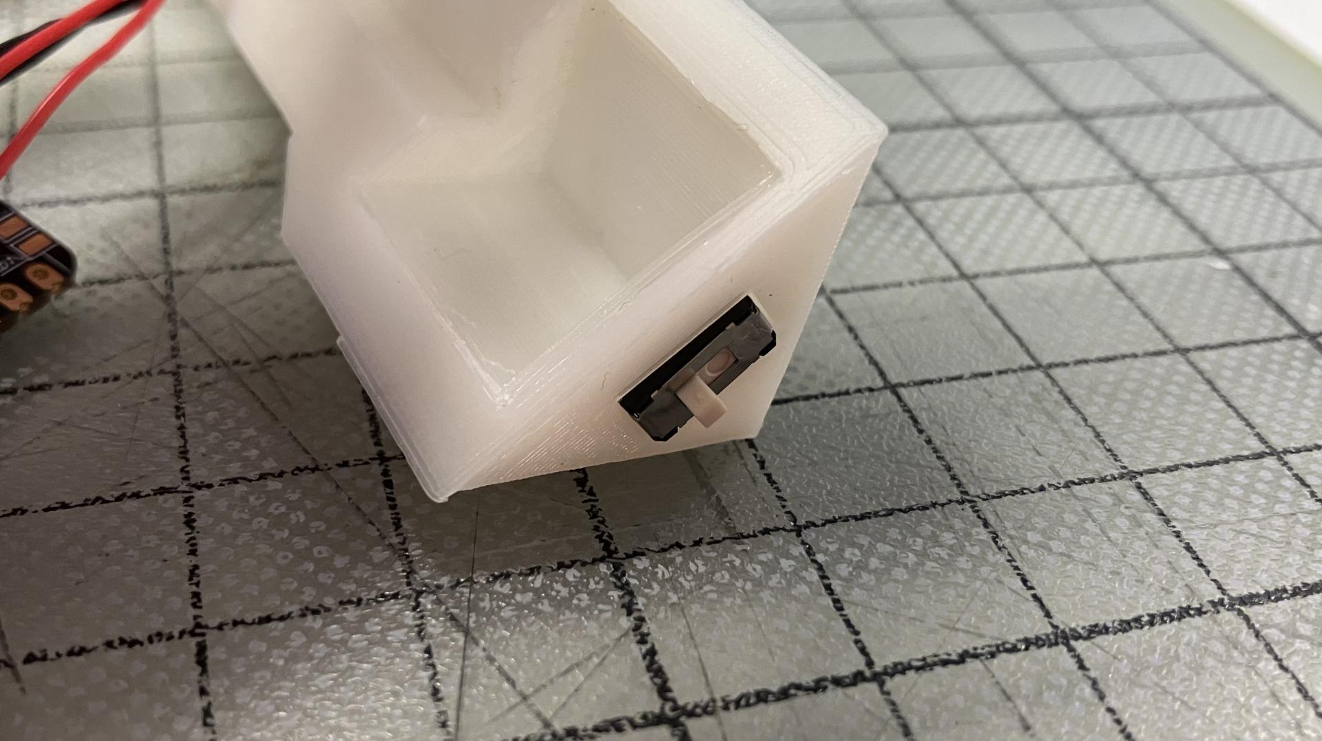
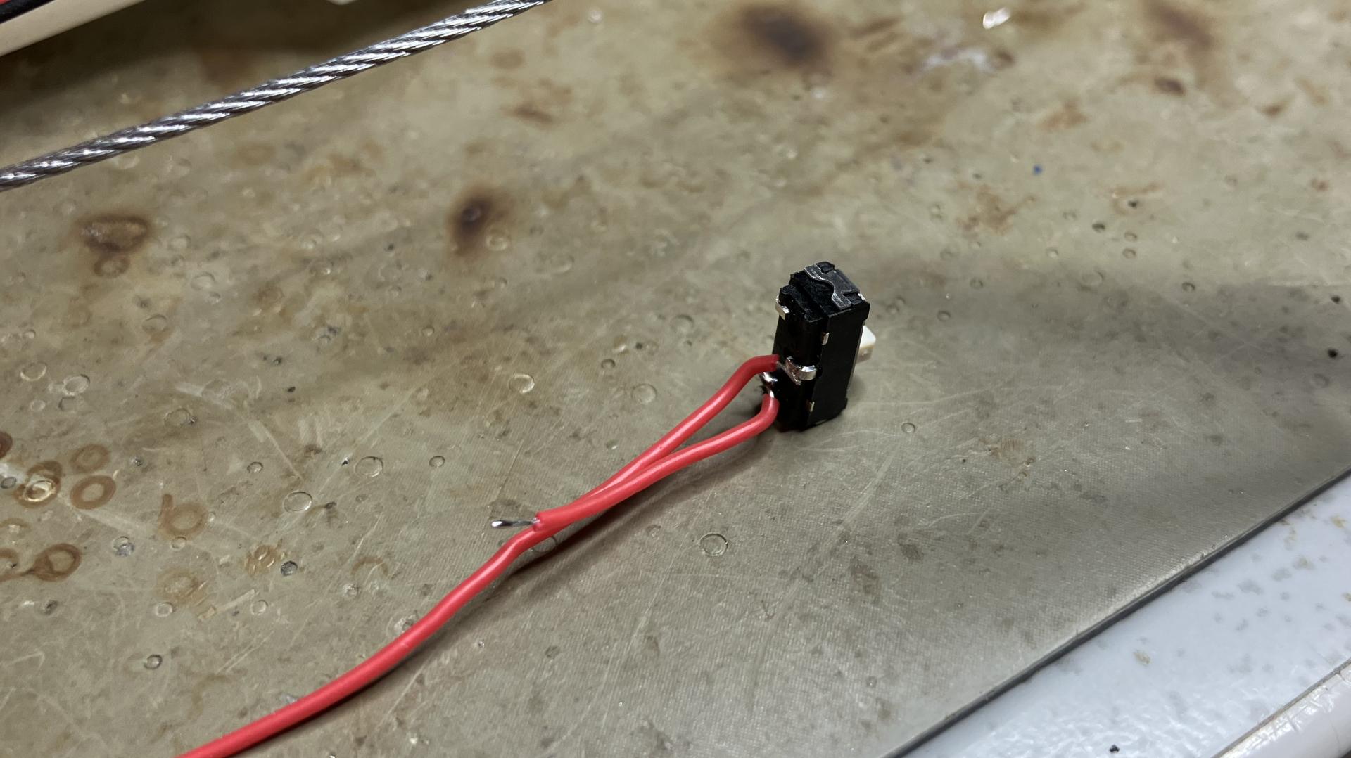
I also wanted to use a slide switch to have the option of switching the stylus on and off. Even though it is said to be optional in the original D-POINT repository, I decided to go for extra effort integrating it as I would prefer not to open the enclosure every time the device needs to be restarted. Surprisingly the C&K JS102011JCQN slide switch from our Fab Academy inventory did fit into the allocated slot almost perfectly.
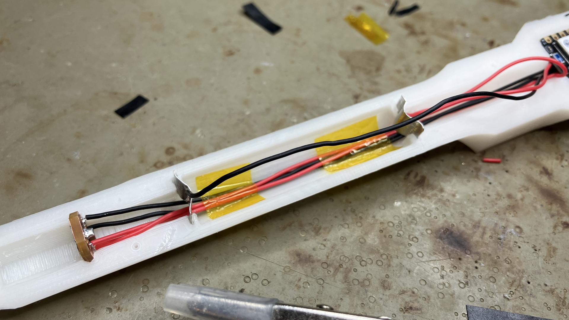
The switch should break the connection before electric current enters the XIAO board. That means one of the wires that is supposed to connect a battery terminal to + or - pad on the bottom of the XIAO board has to be split. Since the switch is placed closer to the board than the battery, the wire has to be split so that there is not too much wire left once the board is put in place.
I did a mistake and soldered the power cables to the XIAO board before putting the switch in place. So I had to de-solder, put the switch in place. I used a small rectangular piece of metal between the wall of the switch and the wall of the pocket for it to reduce play.
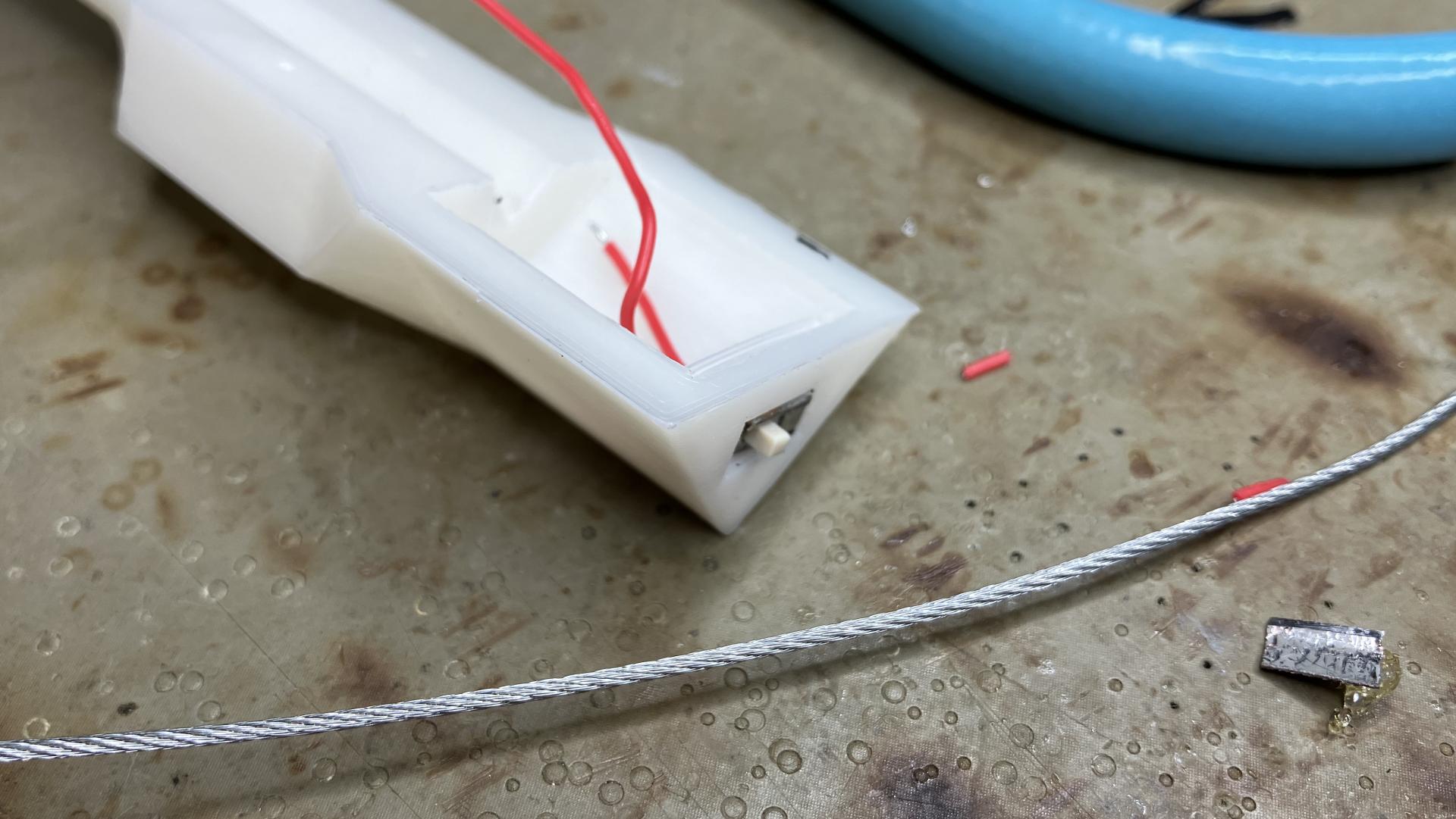
And then the power wires can be soldered to the XIAO board. The XIAO nRF52840 Sense has a battery charging chip on board. With that, it can tell when the battery is low and charge it when the XIAO board has an active USB connection.
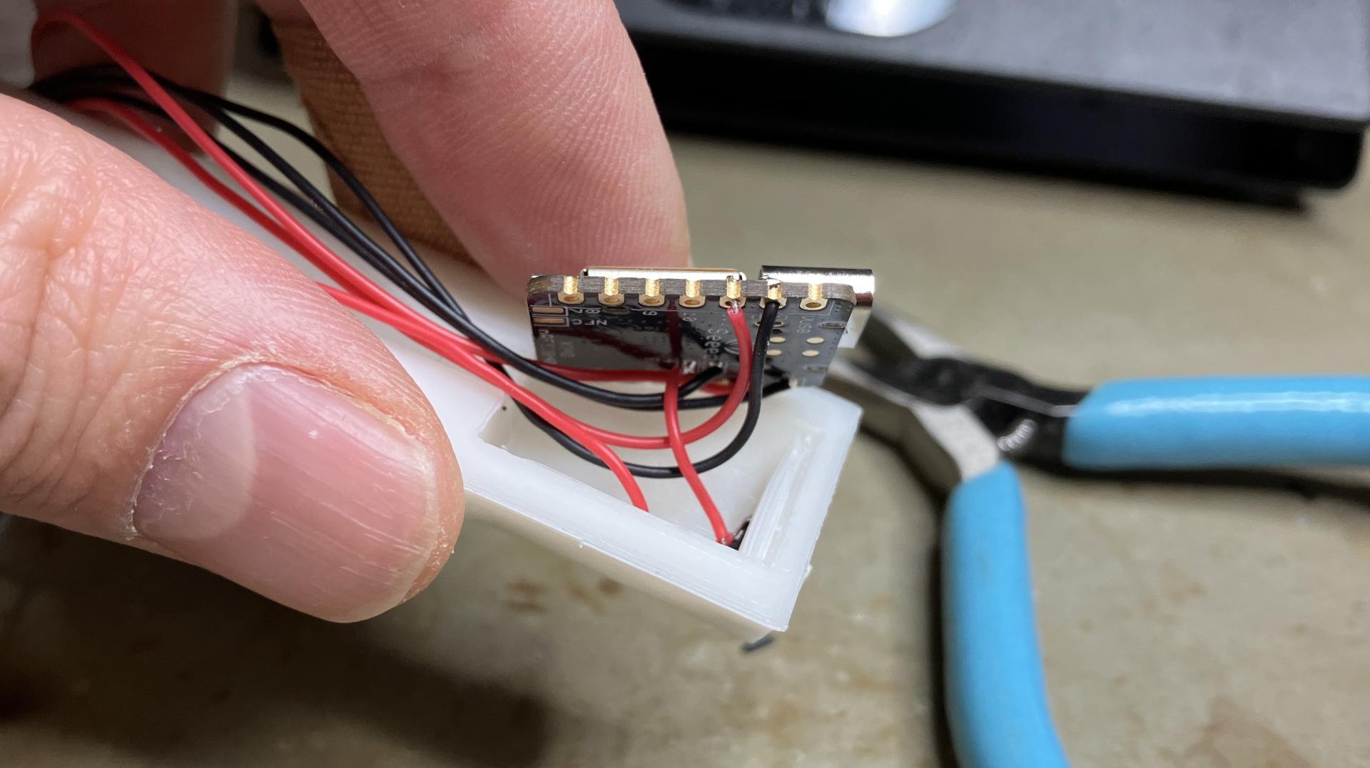
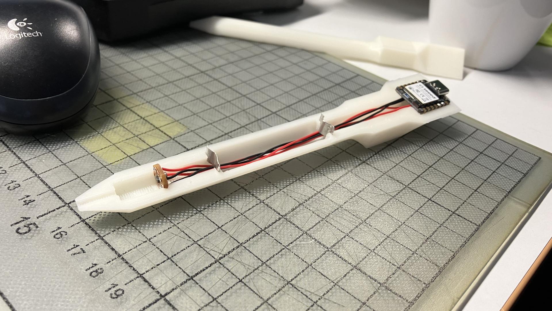
It should be possible to snap the XIAO board in place now. All the cables can be arranged underneath the board, given that the power wire coming from the switch is not too long. Now we have two free wires to be soldered to the battery connectors.
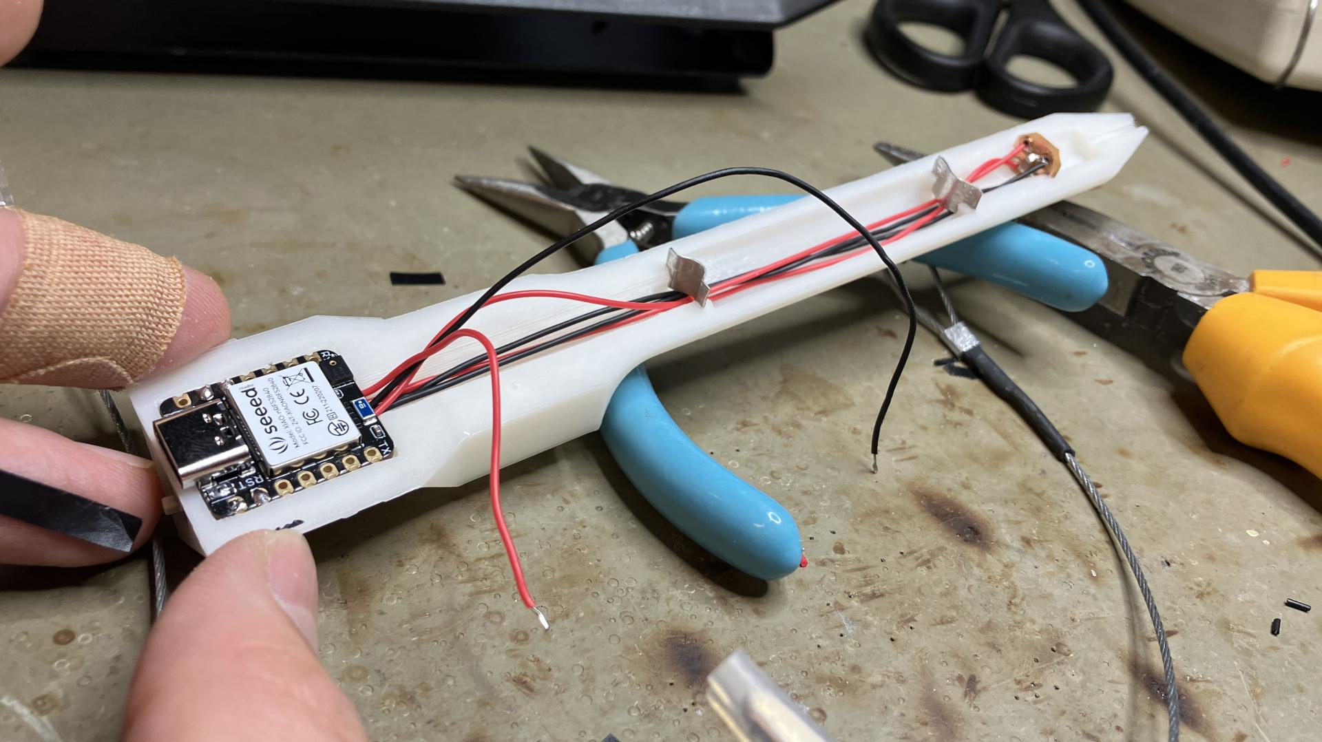
Soldering battery connectors was easy as the metal was taken from existing battery contact clips (Keystone Electronics 555). I added a bit of flux and solder to the clips and wires before soldering them together. I used a bit of capton tape to secure the cables underneath.
At this point I could not resist to upload basic LED blink code to the XIAO board and test if it works with battery alone. And it did!
I carefully attached the top part of the enclosure to complete the build, and having a sturdy on/off switch on the back of the stylus can be very satisfying.
I uploaded the D-POINT code from the repository and it was immediately possible to see it appearing as a Bluetooth device in the SmartDiscover app on my iPhone. I could also see data coming in from the stylus.
Now the visual features. I printed the markers found in the repository on a sticker paper and used a paper knife to cut them apart.
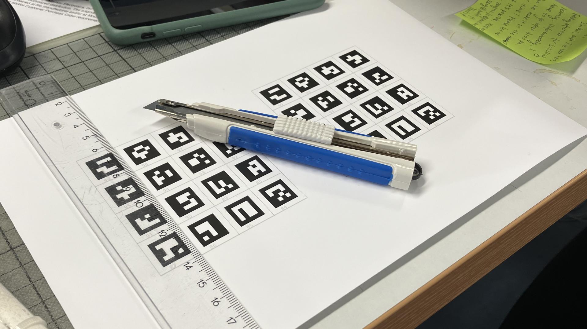
It was easy to figure out where the markers should be placed on the stylus. It is great that they have little, barely visible numbers on the white border that helps with alignment and identification. It is still easier for a human to read a number than decipher a basic fiducial marker.

PCB Production
As for electronics and PCB design, the repository contains all you need to have boards produced online and adjust them if needed. KiCad project along with a local parts library is there and I was able to open it up to make some adjustments that were needed to be able to mill the PCB at the Aalto Fablab using CopperCAM as tool path generator and Roland monoFab SRM-20 milling machine. We are using a 60° 0.2-0.5mm V-bit for isolation milling and a 0.8mm cylindrical tool for all holes starting from 0.8mm diameter up and cutting the board out.
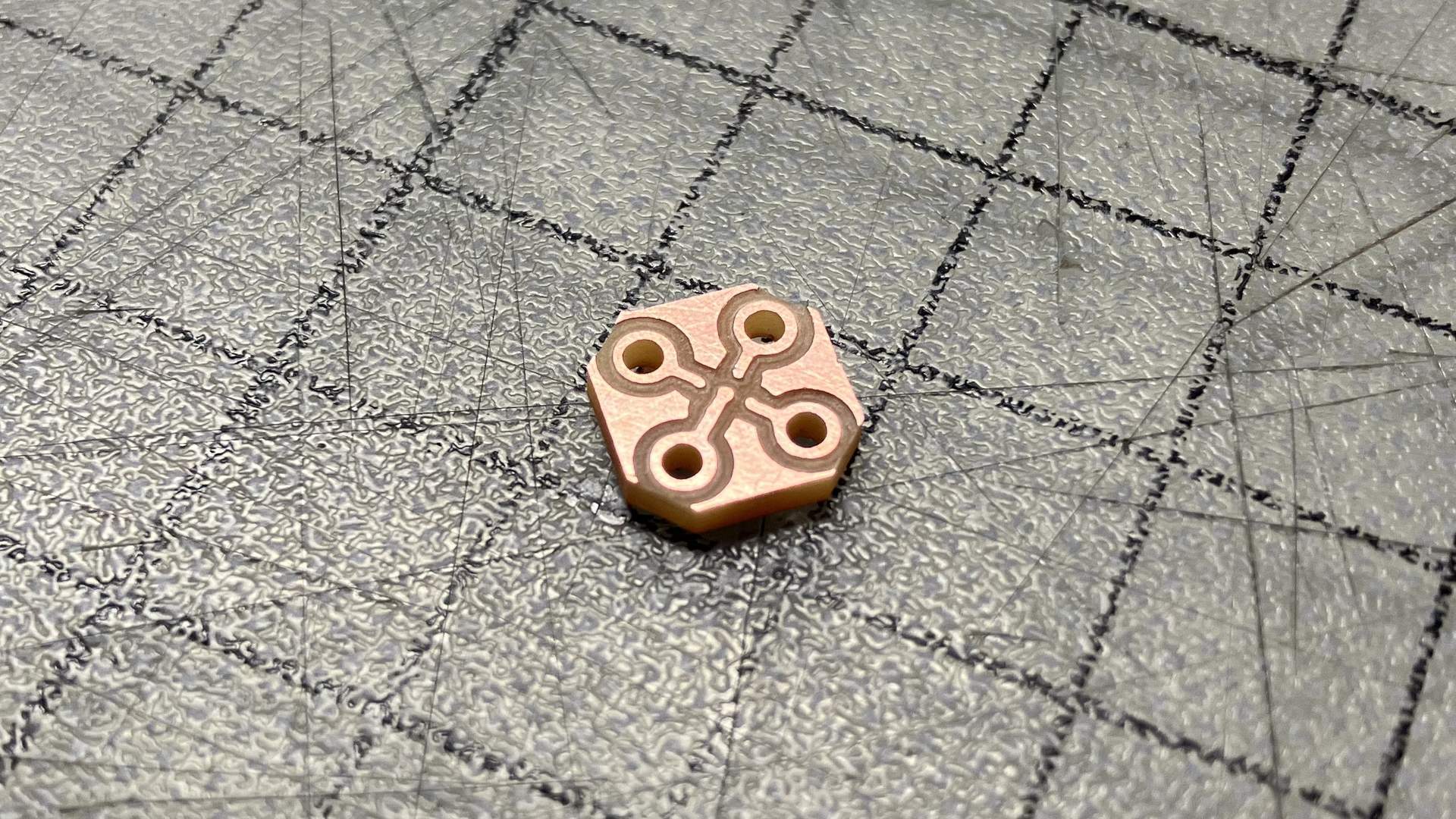
I should add rivets to the circuit board to connect the top and bottom copper layers of the PCB. We use 1.5mm diameter copper rivets for double-sided boards at the Aalto Fablab. They are great to connect the two sides and they also leave a 1.0mm hole in case through-hole components or wires have to be soldered.
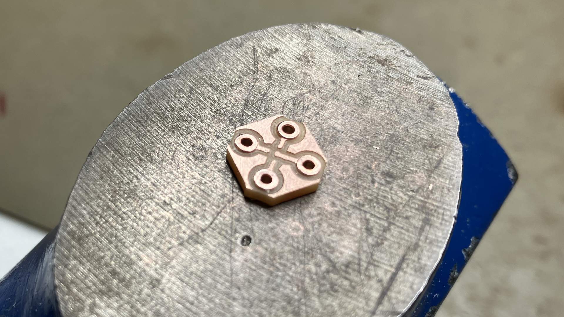
As soon as the force sensors arrived, I tried to use solder paste and hot-air gun to solder it. It seemingly worked, but when placed into the stylus, I was getting random values. So I tried again. The second time I adjusted the design to use 0.8mm rivets. They take less space on the already small board. As for soldering, I first tinned the pads with solder and used hot-air gun to get the solder liquid, before droping the sensor in place.
When that did not work, I tried the third time. This time I also tinned the pads, but just a little and tried to have the same amount of solder on all the pads. I added plenty of flux, placed the component and used the soldering iron to touch each of the traces near each individual pads to heat the solder up so it snaps to the leads of the sensor. It seemed to work well. The sensor still did not give me any readings, so I thought I burned it by using higher than recommended soldering temperature.
I decided to postpone the debugging of the pressure sensor for later as I wanted to get the full stack of things set up to see if it shows any signs of an usable device at all.
Software
First I tried to set it up on my Linux machine and quickly noticed that the code features some Windows-specific Python packages. I removed them from the list of project requirements and, unsurprisingly, had problems running the tracker application.
Luckily, I had a powerful Windows machine available, and I managed to get everything installed without any errors. A window showing live feed from the camera popped up immediately and I could start tracking the stylus right away. This was without powering up the stylus and using its Bluetooth capabilities. This is why the virtual pen does not move yet. I did not run any of the calibration scripts either.
I then tried it with the stylus powered up, and it connected to the computer via Bluetooth. The virtual pen started moving and it did feel like this thing can achieve sub-millimetre accuracy. Unfortunately, it was not possible to see that via the drawing since the start and end of the line would be rather random.
My first thought was that this is most likely due to the pressure sensor, and I will talk more about debugging that in the next section.
Troubleshooting
I did not think much about the device ratings first time I soldered the Alps Alpine HSFPAR003A onto the circuit board. I just tuned up the hot air gun to 300°C and it did the job. The body of the sensor did get a bit sweaty during the process, but I did not mind. When I checked the maximum absolute ratings from the datasheet, I noticed that the recommended soldering curve does not go beyond 250°C. It should have a pre-heat phase of 60-120s with 150-190°C and a 30-50s long heating phase, peaking at 250°C.
Since we use FR2 at the lab, we avoid using the oven for soldering as the material is not as fire-retardant as FR4 used in the industry. Yes, one could order the board online, but I dislike waiting and I would rather try to tackle this little annoying problem with some skill and patience for the sake of solving similar problems to come in the future.
I have made three PCB’s at this moment and they still give noisy readings. Another issue could be the wiring and I am considering to improve that by either getting a thin shielded audio cable or trying to twist the cables connecting the sensor PCB with the XIAO board. It could also be that the soldering joints should be redone. Maybe there is some issue with the cables? I checked the connection with the continuity test, and it beeped. Another solution to this would be integrating an analog-to-digital circuit to shorten the distance the analog signals have to travel, thus avoiding possible interference. This is also discussed in the datasheet of the sensor.
A few more tries with soldering the sensor I suppose. Maybe I should risk and use the oven this one time… For that, I will need to make a solder stencil to apply solder paste. But does the paste melt in 250°C?
I was also thinking about the custom compression spring I made, that it could be too strong. I looked for possibilities to purchase a spring kit similar to the one James mentions in the D-POINT documentation and found one in Puuilo online shop. Let’s see how the new spring can improve what I have.
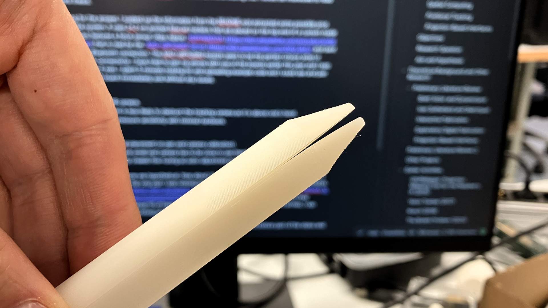
Another problem is the nib. I use a piece of ø1.75mm filament. It does not really snap with the enclosure. There is too much play. So, I am thinking of going to a hobby or more professional sewing shop to look for plastic knitting needles. Those should come in different sizes and have a nice tip. I could then cut them to size and use them.
Another detail that I did not pick up initially was that James recommends to glue a metal or hard plastic piece on the sensor-facing side of the nib base. This is due to the small surface area of the sensing part of the sensor. It extends only 0.1mm above the body of the sensor, so one should be extremely careful to place the nib base in a precise angle.
And then James sent me a few debugging hints.
- Check the voltage of both analog pins. They should be 1/2 the input voltage, both of them, when no pressure is applied.
- Make sure the flat metal surface attached to the nib base is real flat.
- Maybe add a bit of tape around the nib.
I tried the voltage measurement of both of the sensor pins and they were showing 1.6V as expected. It means that there was nothing wrong with my soldering, by the way. Then I used a sacrificial capacitor to acquire a round piece of metal from its body so that I could glue it to the sensor-facing surface of the nib base.
I assembled all together and the system did not behave as expected, so I started wondering again. I wrote a simple test script that samples the analog readings and returns the difference.
#include <Adafruit_SPIFlash.h>
#include <nrf52840.h>
#include <nrf_saadc.h>
#include <nrf_power.h>

void setup() {
  Serial.begin(9600);
  pinMode(A0, INPUT);
  pinMode(A1, INPUT);
}

void loop() {
  int readingA0 = 0;
  int readingA1 = 0;

  for (int i=0; i<50; i++) {
    readingA0 += analogRead(A0);
    readingA1 += analogRead(A1);
  }

  int result = (readingA0 - readingA1)/50;
  Serial.println(result);
}
And it works. So the question now is, why does not the original code work? I went back to browsing the original Arduino code and found this.
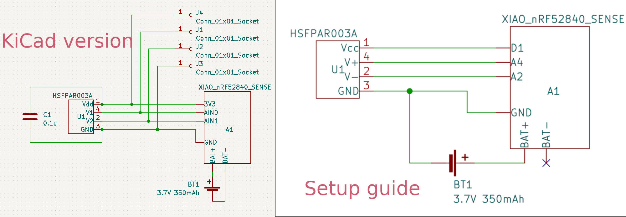
#define PRESSURE_SENSOR_VCC_PIN D1
Excuse me? The D1 pin was supposed to be for one of the sensor pins according to the schematic in KiCad project. And then this.
nrf_saadc_channel_input_set(
	NRF_SAADC,
	PRESSURE_SENSOR_SAADC_CHANNEL,
	NRF_SAADC_INPUT_AIN2,
	NRF_SAADC_INPUT_AIN4);
NRF_SAADC_INPUT_AIN2 and NRF_SAADC_INPUT_AIN4 looks suspicious. So could it be that VCC pin of the sensor board should be connected to D1 on XIAO (not 3.3V), the V+ to A4 and V- to A2? Yes. Exactly. And the diagram in the setup guide shows just that. The problem was that I was guiding my soldering efforts with a schematic from an older KiCad project file.
OK. Resolder everything. And now the pressure sensor works. But the precision is still far from what is expected.
I assume that this could be improved by running the calibration scripts. As instructed, I took 10 pictures with the webcam and put them into the python/calibration_pics/f30 directory. I tried to run the calibrate_camera.py, but ran into errors.
Not able to detect a charuco board in image: /calibration_pics/f30\WIN_20231121_16_07_05_Pro.jpg
Then, I rolled back to the original pictures that could be found in the repository and got another error.
cv2. error: OpenCV(4.8.0) D: \a\opencv-python\opencv-python \opencv\modules \core\src\matrix_wrap. cpp:1667: error: (-215 :Assertion failed) fixed size in function cv::_OutputArray: release'
After a brief moment of using a search engine, I decided to ask James. He responded and told that there is one thing that has not been updated in the current calibration script. charuco_board.setLegacyPattern(True) has to be added. In the calibrate_camera.py script case it would be as follows.
CHARUCO_BOARD.setLegacyPattern(True)
And then it worked. Pictures were opened up one by one, and OpenCV had added some overlay graphics on the detected markers.
I tried to run the app after that and did not see much improvement. I assume that it could be partly because of the flickering of the video stream. At this point the D-POINT software is set to capture at 30fps. Here in Europe (Finland) the indoor lightning is running at 50Hz. I tried to set the Flicker Reduction to 50Hz in Windows 10 camera settings, but it does not seem to affect D-POINT software when run. So, let’s try to change the frame rate in the app.
Changing the FPS in marker_tracker.py from 30 to 25 did nothing. The app FPS still would show around 31fps in the top left corner of the camera view and the flickering would persist. Changing the webcam capture FPS to 50 also did not affect the flickering.
It is interesting that in the camera capture it seems that the the estimated stylus tip is relatively stable, but the virtual pen is much jumpier. camera_delay in app.py could be someting to play with. First, I tried to set it from 5 to 10 and the virtual pen dissapeared.
Reduced it to 4. Better. Went down to 0 one-by-one and no improvement. Seems that 4 gives the best results, but none of the options are real good.
Let’s try to play with the smoothing_length. Initial value is 8, let’s try 4. No change. How about increasing to 16? It is hard to see the change.
I noticed that the virtual stylus tip position does not match the actual one and started to think that maybe playing around with the nib length value could change that. In dimensions.py the STYLUS_LENGTH the initial value is 0.1686. Seems like that is in meters. Changing that to 0.167 seemed to improve projected tip location, but no change in the jumpiness.
At this point, I am losing patience, and I am wondering how to disable the IMU filtering altogether. Visual estimation seems to give me enough precision. It seems that the precision is somehow better when the stylus is straight vertical, but further improvements would probably include many measurements and parameter adjustments. So how to disable the D-POINT filter? Let’s try to understand what values it returns and maybe try to return unfiltered values from the function.
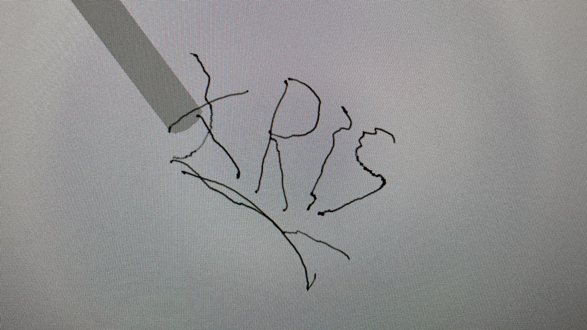
I stop here as I do not want to spend more time on configuration. There is a little success, though – I managed to write my name. It is not exactly my handwriting, but it gives me hope.
Conclusions
As mentioned in the docs, it is not exactly a plug-and-play DIY project. The build was relatively easy, with the pressure sensor and the battery being the potentially hard-to-get parts. Setting up software was not hard, given that one has a powerful Windows computer.
However, after two weeks I do not have a usable input device. I can barely draw a square or write my name with it. The good part is that the visual pose estimation seems to be working fine and with sufficient precision. It is the sensor fusion that has to be tuned before it makes the whole solution usable. There is no easy way to disable the inertial component. Even if it would work, it would work within the D-POINT app and one would need to do extra work to use the position data outside the app.
With that said, still, there are some good takeaways.
- Visual pose estimation seems to work well and can be used in similar solutions.
- Pressure sensitivity works well, but the hardware design could be improved.
- XIAO nRF52840 Sense is a great little board for input device projects.
- Need fancy battery in Finland? Fast? Go to suomenakut.fi.
If I look at the initially assumed pros, all of them are true, except the stylus did not achieve millimeter precision. It looked like that the visual pose estimation would do a good enough job. As for the cons, the calibration and making-it-too-work is a bit too much at this point. The limited distance con is only half-true as with this type of stylus, the work area does not have to be big. And, of course, lightning condition adjustments can take a lot of time, and system-wide webcam flicker reduction was a bit of a mystery.
Otherwise, this was definitely an inspiring build, and I wish to get it to work as it is supposed to at one point. The build process revealed some of the more robust and reusable parts of the system. This to be updated if I get D-POINT working later.